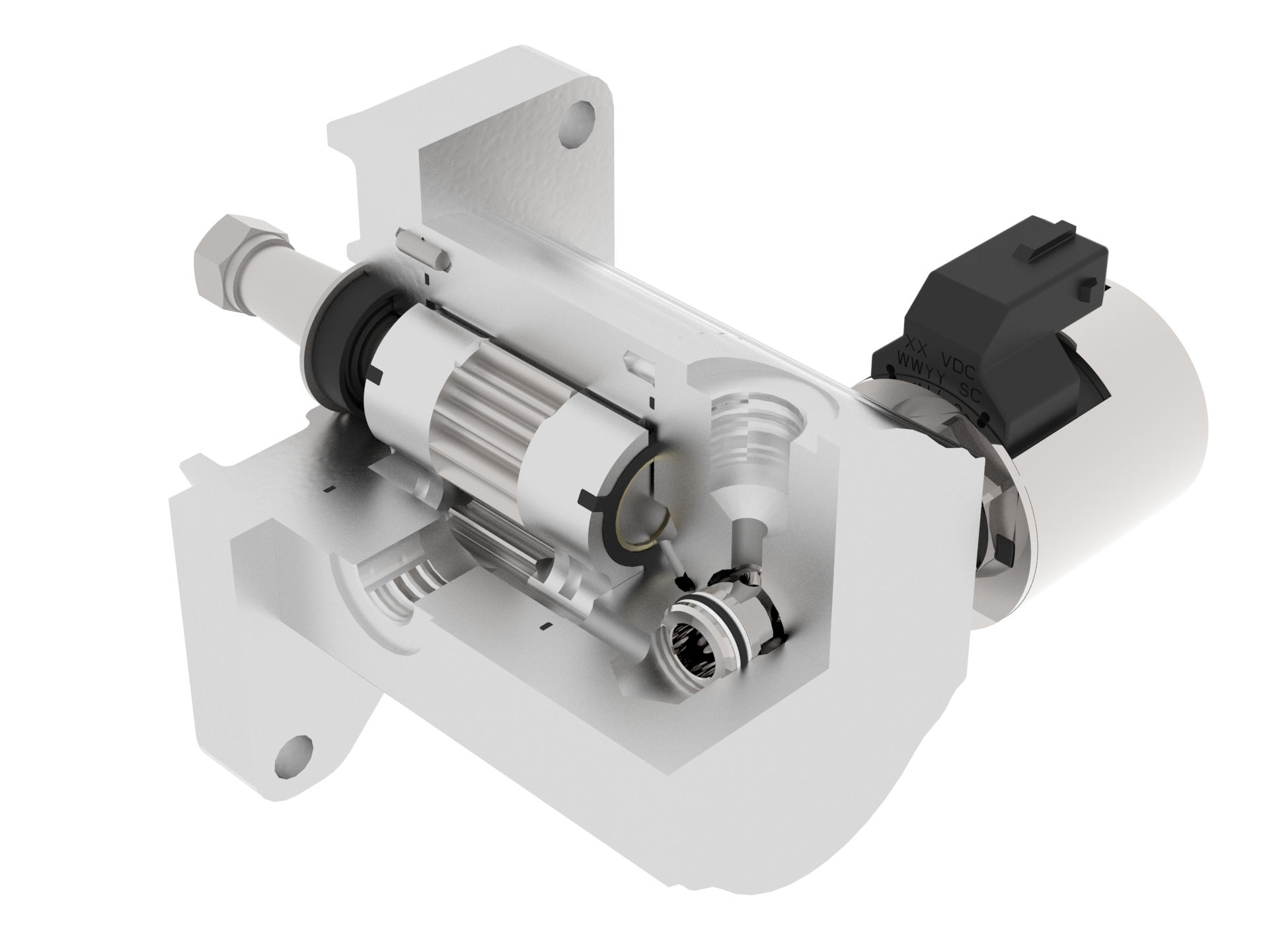
Fan Drive Gear Motors
Hydraulic fan drives have caught on as the most effective way to cool diesel engines. A diesel’s operating efficiency (fuel consumption) and emissions output are closely related to operating temperature. A diesel consumes the least amount of fuel per horsepower produced within a relatively narrow band of temperatures. Likewise, a diesel puts out the least amount of emissions per horsepower within a similar temperature range. So operating the engine within the narrow range of temperatures where the two overlap derives the most power from a diesel engine while minimizing fuel consumption and emissions.
Unlike traditional systems, hydraulic fan drives operate with variable speed. This means air flow through the radiator can be closely matched to the cooling requirements of the engine.
In its simplest form, a hydraulic fan drive consists of a pump, pressure control valve, motor, sensors, electronic control and, of course, all the hydraulic fan drives also allow mounting the radiator in a location that may be more practical than adjacent to the engine. Placing the radiator in a location away from major sources of dirt and contamination means it will stay cleaner longer. Furthermore, fan direction can be reversed when accumulated debris needs to be blown out of the radiator. These characteristics improve cooling by keeping the radiator operating more efficiently. Furthermore, the radiator and fan can be mounted in a location that directs heat away from the vehicle, which can save additional energy by reducing the cooling load on the operator cabin.
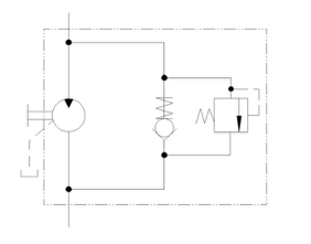
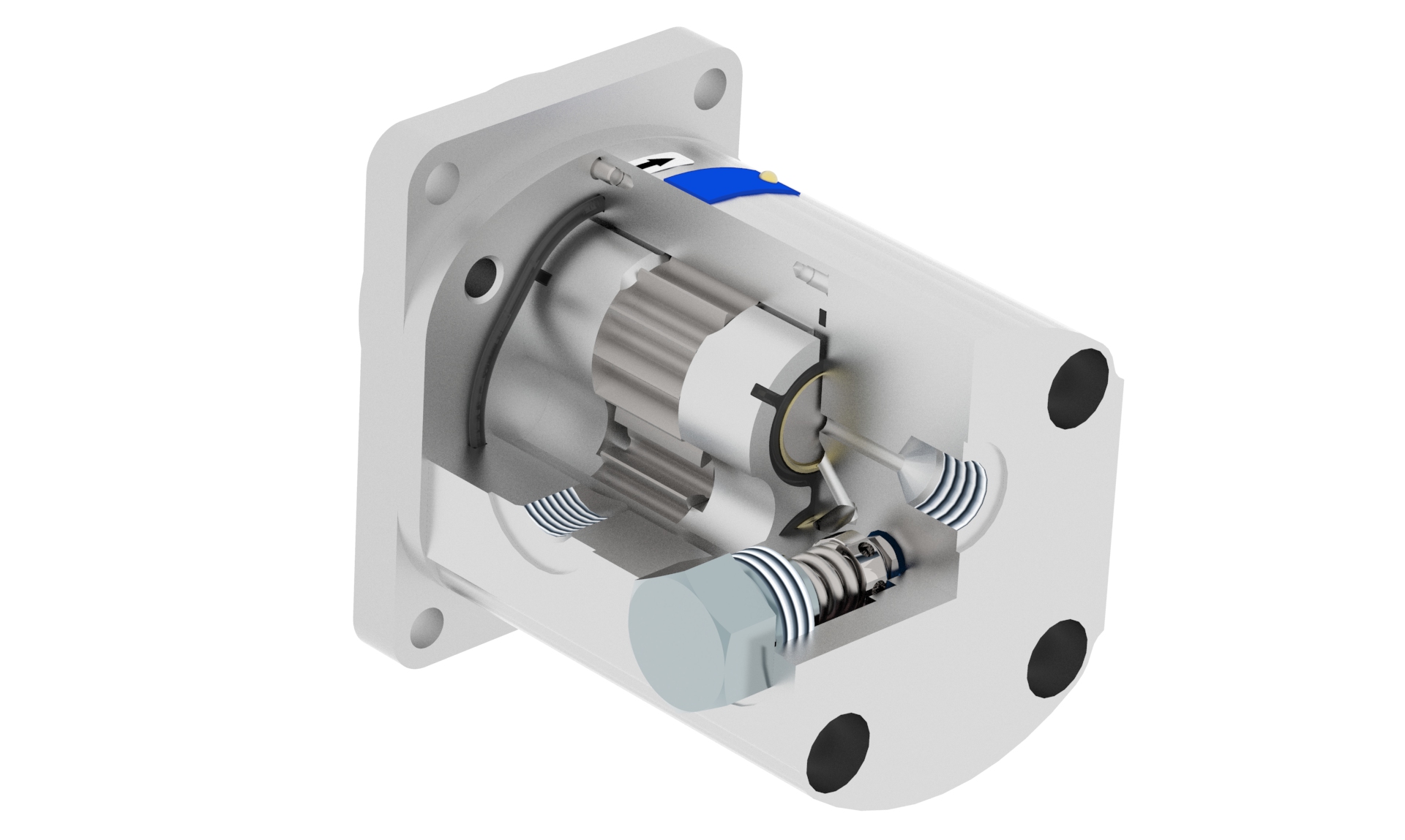
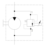
Basic Solution with Combined Relief-Check Valves
- Gear motor with special combined relief-check valves. It has basic safety function, it also works as a check valve
- Revolutions are controlled by external source of the flow
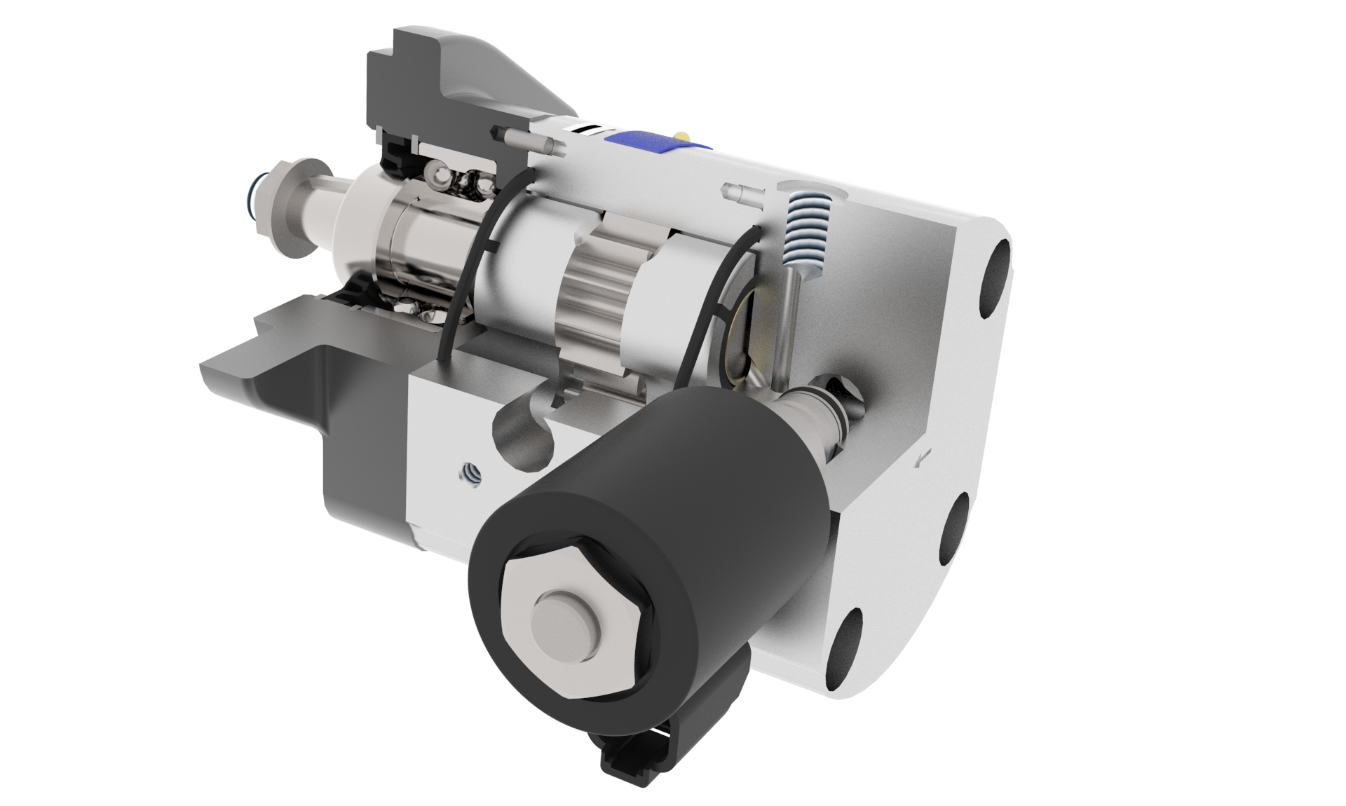
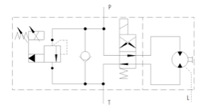
Motor with Proportional Pressure Control Valve
- Gear motor with proportional pressure control valve
- Revolutions are controlled by parallel connected proportional valve
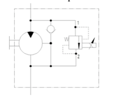
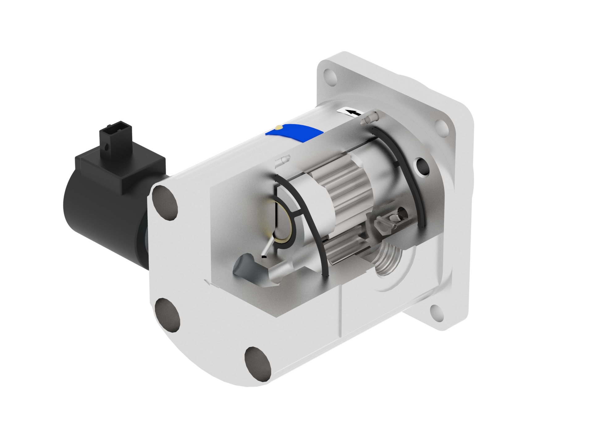
Motor with Proportional Pressure Control Valve and Check-valve
- Gear motor with proportional pressure control valve
- Revolutions are controlled by parallel connected proportional valve
- Designed with internal drain
- The motor is protected by check-valve, which is placed in flange of the motor
Motor with Proportional Pressure Control Valve and Check-valves, bi-directional solution
- Gear motor with proportional pressure control valve and check-valve, bi-directional solution
- Revolutions are controlled by parallel connected proportional valve
- Reverse solution realized by 4/2 solenoid operated directional control valve

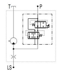
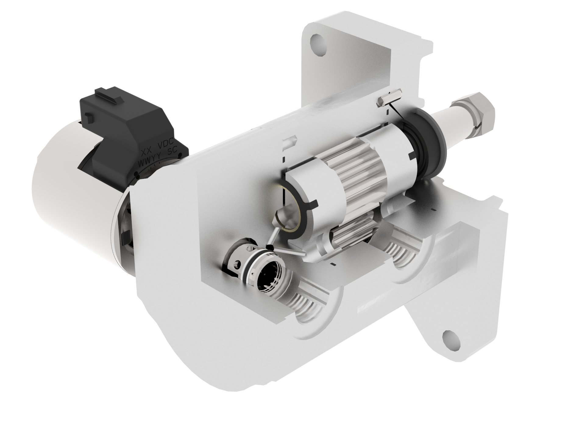
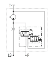
JLM Motor with Proportional Pressure Reducing / Relieving Valve
- Motor with proportional pressure reducing / relieving valve
- Revolutions controlled by by-pass
- Control hydraulic signal for source piston pump leads from the motor input
- Possibility of use in LS signal systems
JLM Motor with high Pressure Proportional Flow Control Regulator
- Gear motor with high pressure proportional flow control regulator
- Revolutions controlled by flow control
- Control hydraulic signal for source piston pump leads from the motor input (same as design of proportional pressure reducing / relieving valve)
- Possibility of use in LS signal systems